

How To Build A True Bypass Loop Pedal

Published: 23/09/2016
Under: Guitar Gear
If you’ve ever wanted to build a simple true bypass loop pedal, it’s not as hard as you think! Also, building one is very cheap as it only requires a handful of components and a box.
Along the way, we’ll also discover how to add a tuner out and master bypass. These advanced features are super useful if you want to build something a little more complex and flexible.
You could buy something premade like the simple Radial BigShot EFX True Bypass Effects Loop Switcher or even a more complex looper like the JOYO PXL4.
However, building a true bypass loop pedal that meets your needs is actually quite simple when you know what you’re doing.
What Tools Do You Need?
You need a few tools including a soldering iron, solder, and wire cutters. If you have a vice, that will help to speed up the process. Also, it’s worth trying to find a piece of wood to work on.
You Need These Basic Components
All true bypass loop pedals have 5 basic components: Mono jack socket(s), 2.1mm DC power socket, 3PDT footswitch, 5mm LED, LED holder, and 4.1k resistor [you will need to match this to your LED]. You’ll also need wire and an enclosure.
You can pick all of these up fairly cheaply and easily. I recommend buying a pre-drilled enclosure, especially if you’re building more than one loop. Not only does this cut down on the time you need to spend, but also ensures the consistency of holes.
Single True Bypass Loop Pedal
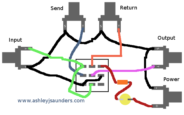
This is the most basic idea and the best starting point. You’ll need 1 x 3PDT footswitch, 4 x Mono Jack sockets, 1 x LED, 1 x Resistor, 1 x 2.1 mm DC power socket, and wire.
Once you’ve wired it all together, you’ll need an enclosure and an LED socket. Again, start with this option as the more complex versions of this circuit are just this one multiplied.
Double True Bypass Loop Pedal
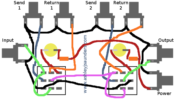
A double looper is just two singles joined together. You can see the output of the first loop feeds the second.
You’ll need 2 x 3PDT footswitches, 6 x Mono Jack sockets, 2 x LED, 2 x Resistor, 1 x 2.1 mm DC power socket, and wire. Also, you’ll need an enclosure and 2 x LED sockets.
Double True Bypass Loop Pedal with Tuner Out/Mute
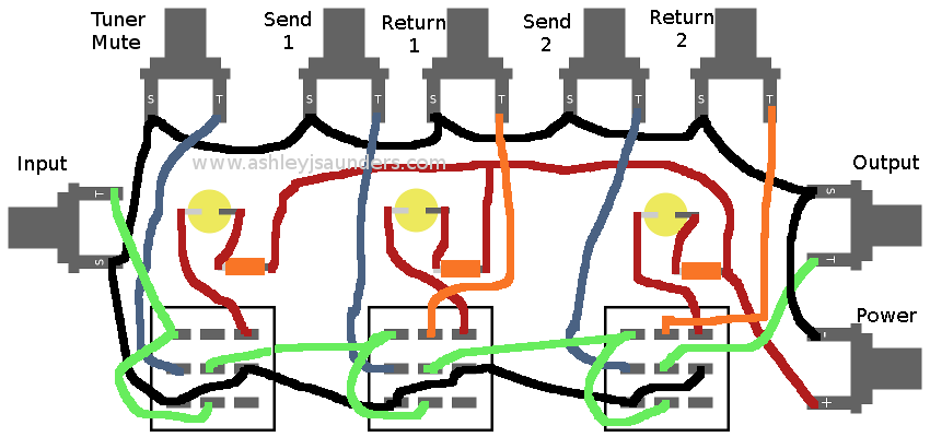
Now, this is just a triple looper with the return of the first loop missing! You can use the tuner loop as a mute for changing guitars or for feeding a tuner so you can silently tune.
You’ll need 3 x 3PDT footswitches, 7 x Mono Jack sockets, 3 x LEDs, 3 x Resistors, 1 x 2.1 mm DC power socket, and wire. Also, you’ll need an enclosure and 3 x LED sockets.
Four True Bypass Loop Pedal with Master Bypass
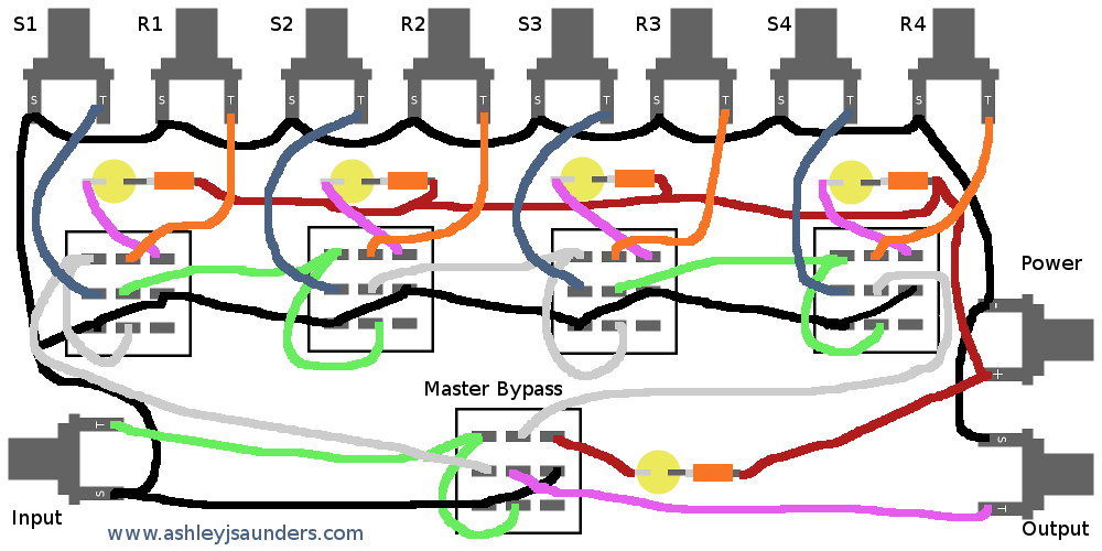
Trying to figure this configuration out, took me a while. I remember trying to kill time on a flight by trying to solve how to add a master bypass.
Basically, the 4 loops sit within one master loop which allows for them to be bypassed. It’s a really cool idea and super useful if you’re running a few different guitar fx pedals.
You’ll need 5 x 3PDT footswitches, 10 x Mono Jack sockets, 5 x LED, 5 x Resistor, 1 x 2.1 mm DC power socket, and wire. Also, you’ll need an enclosure and 5 x LED sockets.
Four True Bypass Loop Pedal with Master Bypass and Tuner Out/Mute

As a highly complex configuration, I’d recommend building each loop on a breadboard and testing as you go. Once you’ve got it working, build and add the next one. You’ll see that I’ve placed the tuner out before the master bypass.
You can use the master bypass function to preset pedal combinations, which you can bring in and out by hitting the master switch.
You’ll need 6 x 3PDT footswitches, 11 x Mono Jack sockets, 6 x LEDs, 6 x Resistors, 1 x 2.1 mm DC power socket, and wire. Also, you’ll need 6 x LED sockets and a super large/custom enclosure.
Success stories!
Since writing this post a few years ago, I’ve gotten a few emails from people who’ve tried to build one of the above or their own modified version of it. I’d love to hear from you if you have any. So, here are some readers’ pictures of their success. Enjoy!


Hi Ashley,
awesome job…I’m intending to convert a Blackstar amp selector pedal into a 3 loop bypass pedal, so super useful.
One thing…can’t find what the power source rating should be for your build (9v, 12v,?)
Typically 9v (as per the standard guitar pedals) but depends on the LEDs and resistors. Glad you found it useful!
This is super helpful! Thank you!
Hope you don’t mind a question: Is the power just for the light? Will the switch work without power (minus LED and resister)?
Thanks! Always happy to help! Yes, your right, it only needs power for the LED(s). So you could build one without power, LED and resistor.
Any particular resistor value? Looks pretty straight forward. I may have missed that value in the article. Can’t wait to try it.
Hi Mike, really depends on the LED you’re using. I believe typically you could use a 100K resistor with a 5mm LED. Hope that helps!
Hi Ashley!
Thanks so much for this info! I built a 5 channel switcher (1 tuner/mute). Used the new switches with LED rings built in and it looks great. Also found a guy on ebay that makes colored nylon washers so I could color code the jacks with the LEDs. Hit a snag with an all metal DC jack (I had handy) until I realized it was not made for center negative and was grounding power to the box. Switched to a plastic jack and it’s working great. Experimented with resistor values for my desired brightness and discovered the green LED was brighter so I needed a higher value for that one to match the others. Now I just need to rewire the pedalboard as things have shifted a bit. Love to send a picture. Looks awesome and I couldn’t have done it without you.
Thanks again,
Mark
Mark, Thanks so much for this. I’d love to see a picture (happy to add it to the article!). Hope you have a cleaner sounding guitar rig thanks to the looper! Ashley
Do these diagrams configuration ground the input.? To eliminate signal bleed over into the bypass.?? Think I read something about that some where.? I’m going to diy a 6 loop switcher without any master bypass or tuner and I’m trying to get my head on straight before I start..thanks.
You need to connect all the grounds to a single point. Good luck, please send me a photo when you’ve built your true bypass looper! 🙂
What resistor value would you recommend for 3mm 12v leds thanks
Hi,
I’d try a 390 ohm resistor. If that’s not bright enough then try 340 ohm or 440 ohm if too bright. But 390 should be perfect. Let me know how you get on!
Hi Ashley,
I followed your example for a double true bypass looper and run a build of it that actually works great when I have all jacks connected to something, it is practically noiseless, but if I did not connect one of the loops it produces a loud and crazy hum, it doesn’t matter which of the lopps are not in use if I Don connect something also just a patch cord to the loop it really hums but if just connect a pedal or a patch on the empty chain it works great. Maybe it is an expected behaviour but I am curious about why this happens.
Thank you a lot!
Hey Arthur, That’s really cool. Thanks for letting me know that you enjoyed building and using a true bypass looper. I think, Arthur that you might have a ground issue. Are all the grounds connected together? Also, you can try adding a ground wire to the enclosure (so long as it’s metal!). Please Let me know if that works?!
Ashley, you are right it was a grounding issue and a really silly actually, I decided to use closed 6.35 jacks, like used on pcb boards the ground issue is that because I accidentally drill my stomp box to close to the edges for the input A and for the output B, I decided to turned them inner side and I soldered the connection to previos – next ground on the chain in a distinct ground pin of the jack , this kind of jacks have 2 ground pins that only closes the ground line when the jack is in use, and that interruption in the ground line was the origin of the hum, I just bridged them and right now is totally noiseless.
Thanks a lot for the help!
Glad I could help! 😀
Hey! Thanks so much for these layouts, definitely making one of these for my next project! Just noticed that the resistor comes AFTER the led in the single bypass, though BEFORE the led in all other diagrams. Is this right? Am I missing something that makes the single work differently?
Greatly appreciate any help, and thanks again for making bypass so accessible!
Hi, it doesn’t matter as you’re wiring in series
Thanks!
Hן Ashley
this looks great and I am looking forward to building one myself.
one question, could you explain how you are connecting your pedals to the Four True Bypass Loop Pedal with Master Bypass and Tuner Out/Mute.
would be great to understand how you are using each to the buttons in relation to the pedals connected.
a video of you using the looper, would be fantastic
thanks
Yuval
Hi Yuval,
I’d wire up the 4 loops with gain based pedals first, then modulation and finally delay. Next, I’d wire the tuner to the specific output.
Hope that helps!
Ashley, thanks for this, it looks absolutely great! I just succesfully build a first version on a breadbord. Just running into one thing: My boss style power adaptor is centre negative (i guess most pedals count on a centre negative power supply). Your schematics count however on a centre positive supply.
Can I just use my negative tip supply, do the build as per your schematics (and just flip the leds)?
Just wondering what this would do to the input and output signal because the positive ground gets send to the amp.
Can you please advise?
regard Richard from the Hague, Netherlands
Hey Richard,
As your only powering the LEDs, the standard center neg power supply will work. I must have written that wrong when drawing up the diagram. Please send me some photos when you’re done.
Ashley
I built this schematic exactly the way it says for the dual looper and tuner bypass but I can’t seem to get it to work. I don’t know if it’s a parts problem. Are their stereo jacks needed in certain spots or certain capacitors?
Hi Jake, sorry but I can’t help without seeing what you’ve done. I do hope you’ve found a solution tho. 🙂
Hey thanks for all the info, I read in the comments that all grounds have to come interconnect. Is that ground coming from the negative DC power input? Also do you have to ground the enclosure at all. Last thing, is their a way to change the pedal order with the switcher without requiring your pedals (ie: putting delay before gain or stacking overdrives differently) or is it only capable of going in the order you wire the jacks and plug in your pedals?
Yes, you want to loop all the negatives together. I haven’t explored your other question, so I can’t help you wire two loops to a single switch that allows you to change the order. I’m sure it possible.
Thanks Ashley really appreciate the response. Do you have to ground the
Enclosure at all?
You shouldn’t need to, but you could.
Hey! I have a weird question… i cant wrap my head around this problem i have. Is it possible to wire together an A/B looper and a single looper seen in this post, under a single switch. How would one work that out exactly…
https://www.taydakits.com/ckeditor_assets/pictures/521/content_dha14v3_wiring.png
http://www.ashleyjsaunders.com/blog/wp-content/uploads/2016/09/Single-True-Bypass-Loop-Pedal.png
I need both of those under a single switch
You’d need to use relays to do this as it’s too complex for simple switches!
Thank you for taking the time to put all of this together.
Do you happen to know how the wiring would be done for an A/B+C switcher? By that I mean two switches, with the first :
switch selecting either A or B (say clean in A and overdrive in B; as indicated by two LED’s and whichever toggle is selected lights up) and then the C switch (e.g. modulation and delay) being added/cascaded as a toggle on top of the A/B?
Hopefully that made sense. Im basically trying to be able to select either clean or dirty with an A/B and then having a second switch to add on delay.
Thanks!
You could build a true bypass loop into an A/B switcher. Another way to do it is to wire the A/B with a send and return (rather than only a send). This way, you can easily flip between two pedals. From there, you could have a true bypass loop for your mod/delay pedal. Hope that makes sense!
Thanks for the layouts, it’s a huge help. Quick question, does the pedal connected to loop 1 flow into loop 2 and so on? Like if I had an overdrive connected to loop 1 and a chorus in loop 2, would this worked the same way as if I used patch cables to run the drive into the chorus pedal?
yes, all pedals are connected in series. So if you have an overdrive in loop 1, chorus in loop 2, delay in loop 3, that the order the signal will flow thro. As a simple solution, you can’t change the signal path without moving pedals around. Hope that makes sense!
Yes thank you! I wanted to make sure this was the case before I wired up the foot switches in the enclosure as my plan is to run my loops starting #1 from right to left. Looking at it now though it appears your already doing that since I guess technically we are looking at the wiring from the back side, not the actual top of the enclosure.
Hi! I just finished a four loops and master bypass pedal. I did notice that the wiring on the fourth switch is wrong: the center pin in the middle column (ground) and the center pin in the right column (signal going back to the master bypass switch) should be exchanged all the way around. I followed the diagram as is not stopping to think about it and it didn’t work so I double checked the diagram and noticed the mistake. But great work anyway, Ashley. Many thanks for the diagrams.
Hector, Awesome! I’ll get that diagram updated asap. Please send me a photo and I’ll add it to this post so others can be inspired by your creation!
Is it really this simple? wouldn’t I need a motherboard to program the loops? how does this work by the diagrams?
Yes, it’s that simple. You can’t do any fancy programing but it any of these will help you stop tap dancing!
Hi Ashley thanks for sharing all this info! I’m building a triple of my own but with a twist. One of my channels is going to be routed towards the FX loop on my amp therefore it has to be isolated from the rest of the channels and the gtr in and amp out, will be using the send and return on the back of the pedal. My question was how would I ground my led and still stay isolated? I’m kinda concerned about creating a ground loop wiring in parallel. If you want I can send you pictures of the build.
I think you’d be fine if you built two separate circuits that sit within the same enclosure. Keep the ground wires separate. Let me know how you get on!
I’m building essential a 4 channel mono with master true bypass and then in the same enclosure I will have 3 more channels but with stereo TRS jacks and 4PDT switches. I still should be able to take 1 leg to ground the led. With the 4PDT I will send the left and right out to the TRS jack for stereo out or in . So basically I will have 2 separate except for the led power supply, two separate looper bypass switches in one enclosure. This will be for my wet dry wet rig kind of EVH inspired.
So basic run down looking at the foot pedal you will have from left to right Stereo in, stereo master, stereo delay, stereo harmonizer, stereo out. Then mono or dry out chorus, octaver, flanger, phaser, master in and in from Wah pedal/Peterson Tuner. To the Tuner/Wah pedals from the decimator pro, before the decimator is my wireless device.,goes into A channel or channel 1.
The mono out from the looper will go through a buffer then into the amp head. I come out of the amp head into a rack mount palmer load box, the pass through to the dry cabinet and the line out into a lexicon pcm70 stereo out, then stereo into the foot switch looper. , back to stereo power amp to the left and right speaker cabinets. Somewhere in there I will have a Mxr 10 band eq. I’m thinking after the palmer or after the lexicon.
Let me know if I’m on the right path. Sorry this was so long. I will also have an interface box from 5 pin XLR pedal snake to 1/4 jacks either mono and TRS also amp selector for the EVH 5150-3.
Steve, yes you’re on the right track. I’d try to build it out on a piece of wood using Crocodile Clips and ensuring it all works. When you’re happy, solder it together and place in the enclosure. Please send me some pictures! 🙂
Well the 4pdt switched didn’t work, basically no led after the stereo ins, out and sends receive. So now I’m back to 3pdt switches with TQ2 style relays, 2 per switch. Those things are tiny. This does everything (on paper) and I did away with the master switches both dry and wet side.
I think but I’m not certain, the 2 wet effects for Cathedral (went to a lexicon pcm70) and the DDLS went to each Roland SDE3000’s but I believe he used midi in TRS form for a single turn on/off the device. It then looped in or out of an interface or loop of some sort. I’m not sure if the lexicon has an input to mute it for the signal pass through or turn it on, same goes for the 2 Roland sde3000’s. I have the guitar world magazine that he was on the cover and it gives a generalized signal chain and effects used but that magical pedal loop seems to be the Holly grail.
I’m waiting on resistors to come in so I can finish my loop pedal. I now have 5 dry and 3 wet. I don’t know how to leave pictures on here. I have finished my pedal snake interface box for the pedalboard.
Do you know any good bare enclosure boxes that are 16 to 18” in length by 3.5”
To 4” wide by 2.5” tall?
Hey Steve, unfortunately, I think you’ll need to go custom as typically enclosures are pretty small. Hope you’re progressing nicely!
Hi Ashley,
How can I make a four-loop true bypass switcher into an A/B/C/D instead? When I press one switch, I want all other loops to go off and only the pressed one to be on. Is that easy?
Thanks,
Ben
Hey Ben, You’d need to use relays for this and be able to programme conditional logic. Sorry!
Got mine working with 5 loops, but ran into a snag (or 2 or 3).
1st snag I figured out was a short on Loop 2, which killed audio when engaged. Thankfully that was easy.
2nd snag is my LEDs aren’t working. I’m fairly new on this side of things and trying to read your diagram got a bit confusing. Is it the negative or positive side of the LED that’s soldered to the switch itself? I’m using 2k resistors for 3mm LEDs as well.
Great project and excited to finally use it!
Hey Joe, The longer LED leg is positive and so needs the current, while the shorter leg is negative and should be connected to the resistor. Try running them from the power input to check they still work and then add to each circuit.
Hi, I have been wanting to buy a one control white looper switcher but this article like the one control white loop swtcher I need 2 loops, 1 more would even better. AND it would need one foot switch to bypass all the loops and just run straight through the pedal to the amp.
Now you have all you need to build your own! 🙂
Hi, one thing I could not see is pull-down resistors. Heard one should use them against the switch popping.
Working on a 2 effect loop and wondering how pull-down resistors might be integrated into the schematics.
Would I need only a single one in the main looper in or out, or would I need one for each in of each loop?
Heard using them at ins would be better than on outs?
The only way to stop the pop, which is a mechanical issue not a wiring one, is to use relays. And while relays are cool and allow you to build additional functions, they are outside the simple ideas in this post!
Hi, and thanks so much for providing exactly what I was looking for!
I’ve never built anything before, and only did a term of electronics in school over 30 years ago-but your post and diagrams have convinced me I should have a go!
I’m going to canibalise some existing switch pedals I have-taking a kill switch and an ABYparralel switch, and some jacks off an old mono Jack simple mixer I had. Between all those I’ll have enough to build the double looper-and as my box already has 2 switches, we’ll stick there!
I definitely intend to pop back and let you know how I get on (and whether I had to enlist help from my technologist friends! ).
Thanks again for this most useful post!!
All the best,
Michael
Hey Michael, Good luck and please do report back! 🙂 Ashley
I intend building a Four True Bypass Loop Pedal with Master Bypass and Tuner Out/Mute as described in your last diagram but i cannot figure out how you you use the tuner out section,do you have to use a seperate guitar lead fron instrument to tuner socket. Any help in explaning how it works would be very much appreciated.
Hey Paul, the tuner out allows you to connect a cable from that socket to your tuner. You can then use the footswitch to mute your signal while routing it to the tuner.
Hi, how would you wire a looper with blend control? Yes, it’s a bass thing.
The best place to add a blend circuit to a loop is after the return jack. You’d need to feed the circuit with a direct feed from the send jack to allow you to blend the clean signal with the FX. Let me know how you get on!